Architecture
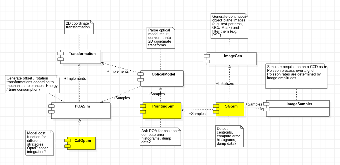
The first step performed during the design phase was to identify the different software components that would conform the final project. The components identified during the design phase, along with their depencies, are illustrated below. Components referring to command line tools are highlighted in yellow.
Common
The common component represents the set of generic utility classes used across the project, like float array, exceptions and quantities.
-
class
FloatArray(shape, buffer=None, offset=0, strides=None, order=None)¶ Convenience subclass of
numpy.ndarraywith helper methods that ensures all arrays created from miscellaneous Python objects like tuples or lists are of the sameARRAY_TYPEtype. Currently,ARRAY_TYPEis defined asfloat32, giving a 24-bit significand (slightly more than 7 decimals of precission). This class also provides a unified way to define tensors inharmoni-pmConstructor parameters are that of the underlying
numpy.ndarrayconstructor withdtypeset toARRAY_TYPE.-
static
make(lst)¶ Factory method that instantiates a
FloatArrayfrom a given Python list or tuple specified bylst. Thislstis passed directly to the underlyingnumpy.ndarrayconstructor, and therefore the usual list/tuple -numpy.ndarrayconversion rules apply.
-
static
compatible_with(arr)¶ Returns True if arr is derived from numpy.ndarray and its dtype is set to ARRAY_TYPE. Otherwise, return false.
-
static
-
class
Configuration
-
class
InvalidPrototypeError
-
class
InvalidTensorShapeError
-
class
QuantityType
Transformation
The Transformation component provides the abstraction to handle coordinate transforms between conjugate planes, assuming Gaussian optics (i.e. diffractive effects are ignored and must be modeled separately). Under this approximation, transforms are just \(\mathbb R^2\to\mathbb R^2\) functions between coordinates.
Something as simple as a telescope with a given focal length can be modeled as a coordinate transform that multiplies the input coordinates by the inverse of the focal length. The following clases belong to the Transformation component:
-
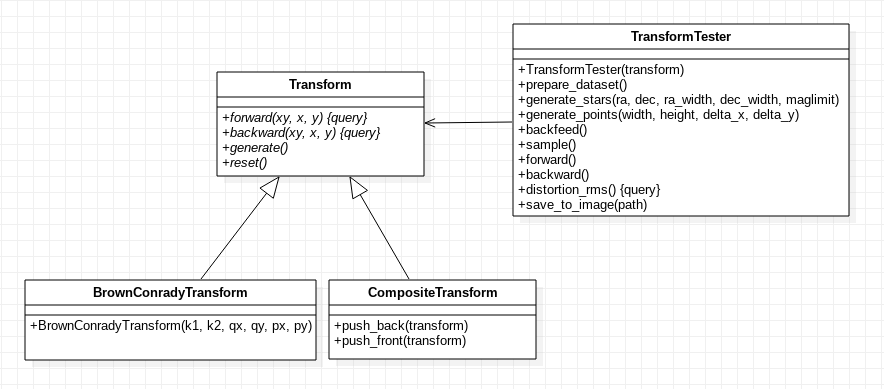
class
Transform¶ This is the abstract class from which all other coordinate transforms are derived. If instatiated directly, it represents the identity transform. Transforms accept tuples of the form \((x, y)\) or \(N\times2\) FloatArray arrays representing sets of \(N\) coordinates.
-
_forward(xy)¶ Protected method that computes the forward transform over the
ARRAY_TYPEtuplexyand returns a \(1\times2\)FloatArraycontaining the transformed coordinates. Non-trivial derivations ofTransformmust override at least_forwardand_backward.
-
_backward(xy)¶ Protected method that computes the backward transform over the
ARRAY_TYPEtuplexyand returns a \(1\times2\)FloatArraycontaining the transformed coordinates. Non-trivial derivations ofTransformmust override at least_forwardand_backward.
-
_forward_matrix(matrix)¶ Protected method that performs \(N\) forward coordinate transforms all at once over the coordinate list
matrixin the form of a \(N\times2\)FloatArrayand returns the transformed coordinate list as another \(N\times2\)FloatArray. If not overriden by the subclass, this method simply applies_forwardalong the \(N\) rows ofmatrix.
-
_backward_matrix(matrix)¶ Protected method that performs \(N\) backward coordinate transforms all at once over the coordinate list
matrixin the form of a \(N\times2\)FloatArrayand returns the transformed coordinate list as another \(N\times2\)FloatArray. If not overriden by the subclass, this method simply applies_backwardalong the \(N\) rows ofmatrix.
-
forward(xy=None, x=None, y=None)¶ Public method that performs a forward transform, accepting either two scalar coordinates
xandyor a tuple /FloarArrayof coordinates inxy. The method automatically determines whether to use_forwardof_forward_matrixaccording to the arguments passed to it.
-
backward(xy=None, x=None, y=None)¶ Public method that performs a forward transform, accepting either two scalar coordinates
xandyor a tuple /FloarArrayof coordinates inxy. The method automatically determines whether to use_backwardof_backward_matrixaccording to the arguments passed to it.
-
generate()¶ In case the transform is derived from a set of parameters with uncertainties (e.g. mechanical tolerances, misalignments, precission limits in measurements), this method is called during Monte Carlo testing to initialize the specific transform parameters by drawing a sample from each parameter distribution.
-
reset()¶ In case the transform holds a state (e.g. energy consumed during operation, time variation of the parameter distributions, etc), this method sets any internal state variables to their initial values.
-
-
class
CompositeTransform¶ The
CompositeTransformrepresents a chain of transforms \(T_{1},T_{2}, ... ,T_{n}\) that are applied sequentially according to the transform direction. If \(T_1\) represents the coordinate transform between the object plane and the rest of the chain and \(T_n\) the transform between the rest of the chain and the object plane, the forward composite transform is simply \(T_{cf}=T_{nf}\circ \dots \circ T_{2f}\circ T_{1f}\). The backward transform will be \(T_{cb}=T_{cf}^{-1}=(T_{nf}\circ \dots \circ T_{2f}\circ T_{1f})^{-1}=T_{1f}^{-1}\circ T_{2f}^{-1}\circ \dots \circ T_{nf}^{-1}=T_{1b}\circ T_{2b}\circ \dots \circ T_{nb}\).-
push_front(T)¶ Puts the transform
Tin the frontmost position of the transform chain, becoming the first transform to be computed in the forward direction.
-
push_front(T)¶ Puts the transform
Tin the backmost position of the transform chain, becoming the first transform to be computed in the backward direction.
-
-
class
TransformTester(T)¶ As new transforms are expected to be implemented in the future, a tester class
TransformTesterwith transform debugging functions is provided.TransformTesteris instantiated from a given transform \(T\) and can generate a set of coordinates (the so-called departure coordinates), either from a regular grid or from a set of stars in the sky up to certain visual magnitude. Then, a copy of these coordinates (the current coordinates) can be transformed multiple times in both directions by applying \(T\) by means of the tester API. Finally, the tester API also allows the user to measure how much the current coordinates deviate from the departure coordinates and produce image files representing these deviations.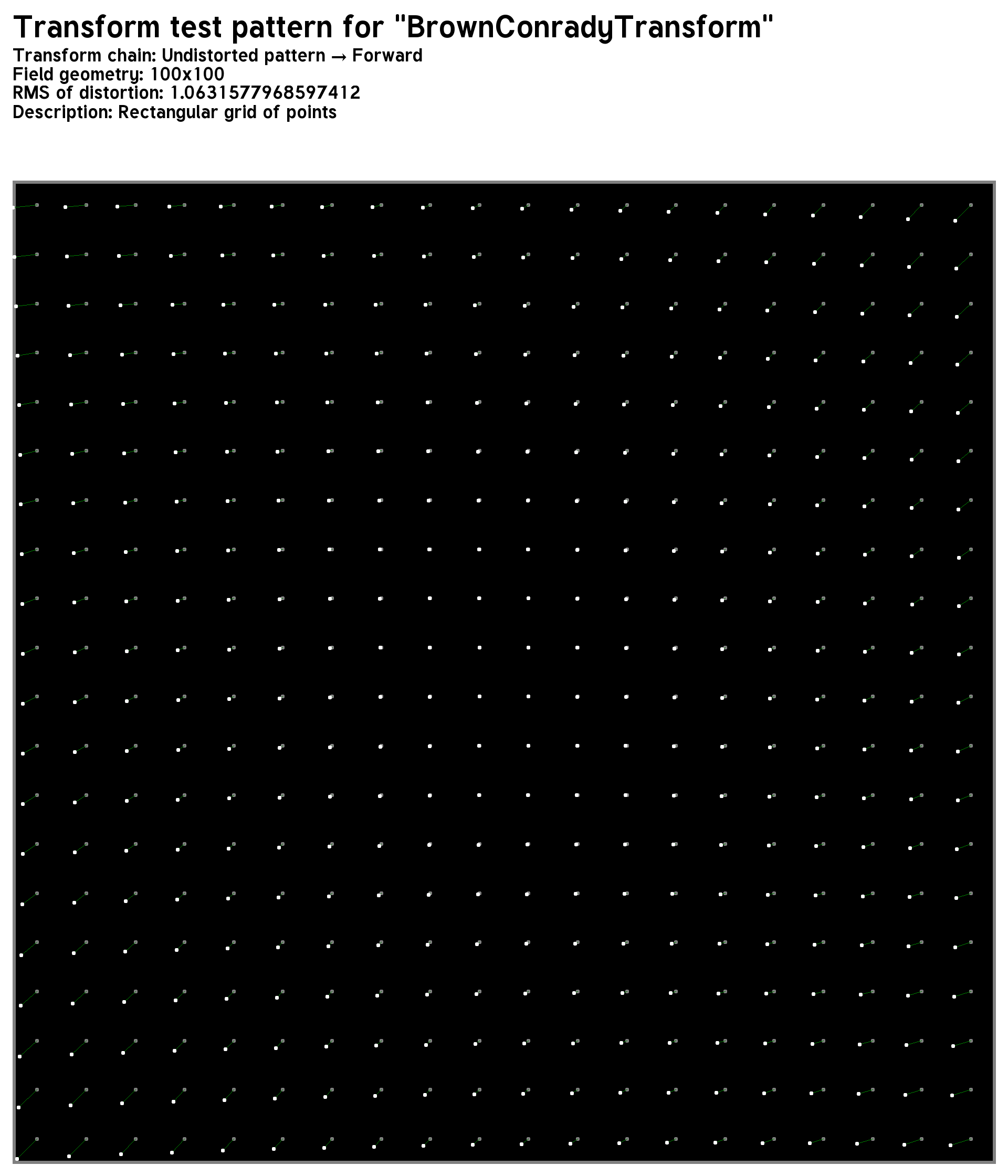
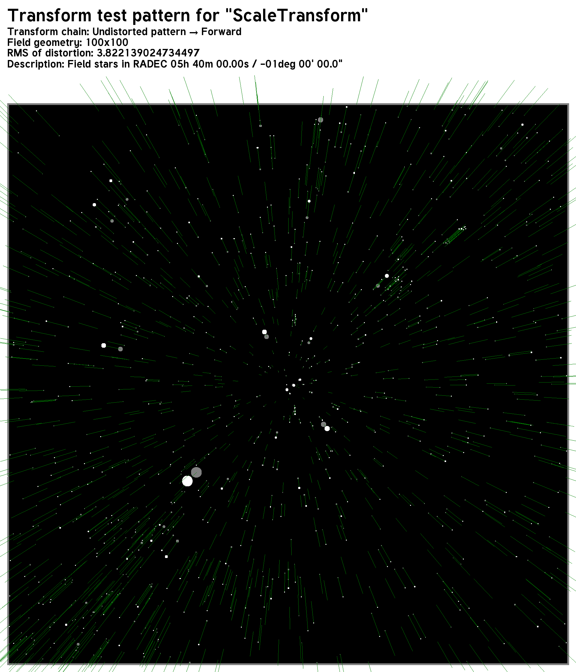
Images produced by TransformTester using a regular grid of points (left) and stars in the sky (right).
-
generate_stars(ra, dec, ra_width, dec_width, maglimit)¶ Initializes the departure coordinates from a set of stars in the sky enclosed in a rectangle centered in right ascension
raand declinationdec, and dimensionsra_width x dec_width(both of them in degrees) up to magnitudemaglimit. Right ascension is encoded in the \(x\) coordinate and declination in the \(y\) coordinate.
-
generate_points(width, height, delta_x, delta_y)¶ Initializes the departure coordinates from a set of equally spaced points, assuming a rectangle of size
width x heightwith adelta_xseparation in the horizontal dimension anddelta_yseparation in the vertical dimension.
-
forward()¶ Applies the transform
Tto the current coordinates in the forward direction and replaces them by the result of the transform
-
backward()¶ Applies the transform
Tto the current coordinates in the forward direction and replaces them by the result of the transform.
-
backfeed()¶ Replaces the departure coordinates by the current coordinates, effectively behaving as if the tester departure points were generated from the current state.
-
sample()¶ Call
T.generate()in order to sample the parameter distribution of the transform.
-
distortion_rms()¶ Returns the root-mean-square value of the difference between the current coordinates and the departure coordinates. This value is computed as:
\[E = \left[\frac{1}{N}\sum_{i=1}^N (x_i-\tilde{x}_i)^2+(y_i-\tilde{y}_i)^2\right]^{1/2}\]With \((x_i, y_i)\) the departure coordinates and \((\tilde{x}_i,\tilde{y}_i)\) the current (potentially transformed) coordinates.
-
save_to_image(path)¶ Produce an image describing the result of the transformation with respect to the departure points, along with technical information like the exact sequence of applied transformations and the transform RMS.
-
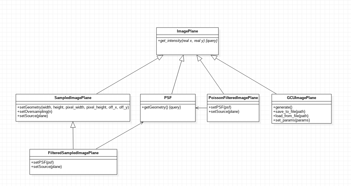
ImageGen
The ImageGen component provides an abstraction for images both in the sky and the focal plane called Image Planes indistinctively. In this context, an Image Plane is simply a radiative intensity field \(I(\vec{q}): \mathbb R^2\to\mathbb R\), where \(\vec{q}=(\alpha,\delta)\) if the field describes objects in the sky, or \(\vec{q}=(x,y)\) if the field refers to the intensity in the focal plane.
Image planes are transformed by the optical model and sampled by ImageSampler, which takes into account focal distances, obstructions, entrance pupils, etc. and determines not only how much light arrives to the focal plane, but also how sky coordinates are translated into focal plane coordinates and the intensity is converted into flux.
The intensity returned by image planes, as well as of the rest of magnitudes handled internally by harmoni-pm, has SI units (\(\text{J m}^{-2}\text{sr}^{-1}\text{s}^{-1}\text{Hz}^{-1}\)).
-
class
ImagePlane¶ Base class for all implementations of image planes.
-
class
GCUImagePlane(params=None)¶ Specialization of
ImagePlanethat attempts to reproduce the intensity map of a regular grid of homogeneously-illuminated circles, mimicking the GCU mask of the instrument. If specified,paramsis a dictionary whose keys describe parameters to be adjusted. Unrecognized parameters are ignored. Accepted parameters are:point.separation: separation of the circle centers in both dimensions (\(\text{m}\)). Default: \(15\times10^{-3}\)point.diameter: diameter of each circle (\(\text{m}\)). Default: \(150\times10^{-6}\)point.intensity: intensity of each circle (\(\text{J m}^{-2}\text{sr}^{-1}\text{s}^{-1}\text{Hz}^{-1}\)). Default: \(10^{-3}\)point.x0: horizontal displacement of the mask (\(\text{m}\)). Default: \(0\)point.y0: vertical displacement of the mask (\(\text{m}\)). Default: \(0\)mask.diameter: diameter of the mask (\(\text{m}\)). Default: \(0.4\)
-
generate()¶ Initialize the GCU by drawing random samples from its parameter distributions.
-
save_to_file(path)¶ Save parameters to a file.
-
load_from_file(path)¶ Retrieve parameters from a file.
-
set_params(params)¶ Updates the GCU parameters according to the dictionary specified in
params(see constructor for details).
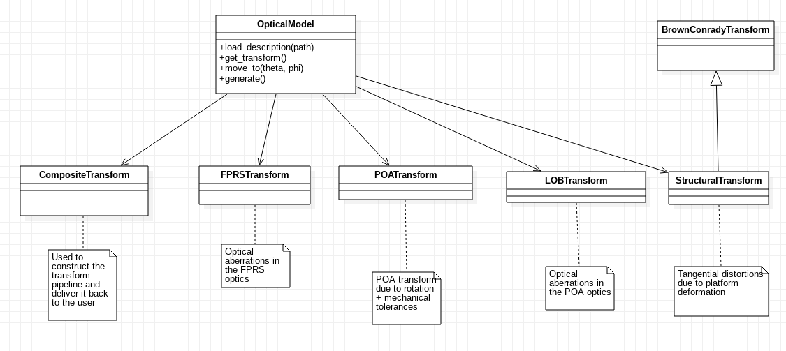
OpticalModel
The optical model is responsible for integrating known information about the instrument that may affect the behavior of the optics between the entrance pupil and the CCD. This information may include mechanical tolerances, optical aberrations, thermal effects, etc. along with their corresponding uncertaintites. As a result, the optical model produces a coordinate transformation between the entrance pupil and the exit pupil.
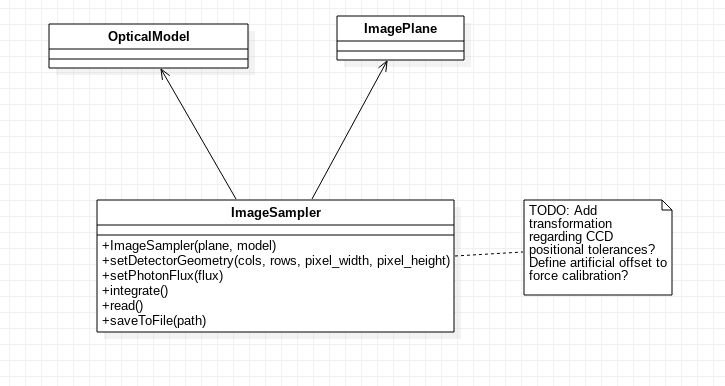
ImageSampler
The ImageSampler component attempts to reproduce the image acquired by a CCD assuming an intensity field given by an ImagePlane object is placed in the entrance pupil of the optical model described by an OpticalModel object, simulating the image produced by the instrument. The ImageSampler is also in charge of translating the input intensity map into a flux map that can be used to integrate the image in the CCD.
-
class
ImageSampler(plane, model)¶ Initializes the
ImageSamplermain object, from a given sky/maskImagePlaneas first argument andOpticalModelas second argument. TheImageSampleris set with a default oversampling value ofHARMONI_IMAGE_SAMPLER_OVERSAMPLIGN(currently 8). Parallelization is set to true by default.-
set_oversampling(oversampling)¶ Sets the oversampling value to
oversampling. This operation triggers the precalculation of all intermediate data like the coordinate offset matrices and the CCD matrix.
-
set_geometry(cols, rows, delta_x, delta_y, finv=1)¶ Sets the geometry of the CCD to
colscolumns wide,rowsrows tall, and with pixel sizesdelta_xxdelta_y, both in meters. The optional argumentfinvestablishes adjusts the plate scale between the last optical element in theOpticalModeloptics and the CCD.
-
set_parallel(val)¶ Enables or disables parallelization according to the boolean value
val.
-
integrate()¶ Triggers integration of the sky intensity function passed to the constructor, in a serial or parallel fashion according to the current parallelization configuration. Returns a tuple with the following information, in order:
Number of slices of the CCD.
The mean computation time of each integration slice.
The standard deviation of the computation time of all slices.
Total integration time (in seconds).
TODO: specify integration time!
-
integrate_serial(): Force computation of all slices in one thread (equivalent to calling
integrate()with parallelization disabled). No value is returned.
-
integrate_parallel(): Force computation of all slices in one thread (equivalent to calling
integrate()with parallelization enabled). No value is returned.
-
save_to_file(path): Saves the image produced by the CCD to an image file specified by
path.
-